

Understanding hull cross section shape independent of foils
Think of it too in terms of the units
In the following discussion we will look at the principles influencing cross section shape.
As mentioned in Part 1, the extremely high length to beam (slenderness) ratio of each A Cat hull reduces the relative importance of wave making drag as a component of total drag. This is equivalent to saying that friction drag due to wetted surface is more dominant.
In very simple terms, the hulls are so long and skinny that they push very little water out of the way for their weight. So friction due to wetted area accounts for more of the total drag than on less slender types.
In very simple terms, the hulls are so long and skinny that they push very little water out of the way for their weight. So friction due to wetted area accounts for more of the total drag than on less slender types.
Ideal underwater cross-sectional shape would therefore be a semicircle because it gives the least wetted area for a given volume.
Strictly speaking, a semicircle gives the shortest perimeter to the cross section, the cross section being a two dimensional shape.
Strictly speaking, a semicircle gives the shortest perimeter to the cross section, the cross section being a two dimensional shape.
Think of the units:
Waterline Beam (m) X Depth (m) = Area (m2)
Waterline Beam (m) X Depth (m) = Area (m2)
Area (m2) X Waterline Length (m) X Prismatic Coefficient (dimensionless coefficient) = Volume Displacement (m3)
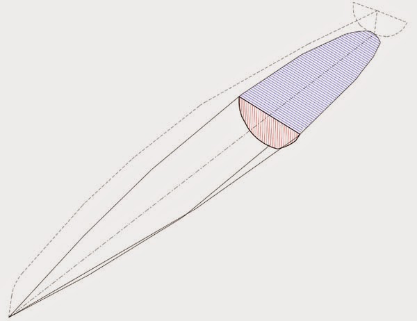 |
| Underwater cross section shown in red. Waterplane in blue. The perimeter of the cross section is the edge of a slice through the surface of the hull at any given longitudinal location. Think of a string placed on the hull along the edge of the cross section. For a given volume, a semicircular cross section will give the shortest string. When multiplied out by length, that gives the smallest wetted area. The width of the cross section at the waterline determines the waterplane area. In this diagram the cross section is approximately semicircular (twice as wide as it is deep). A given cross-sectional area can be obtained with a range of shapes. |
Trends
The generation of boats immediately before the current one tended to semicircular sections but the latest boats have moved to more rectangular sections.
On the face of it this is counter intuitive, but it makes sense when viewed together with the fact that overall volume has been increasing.
As rigs have developed and sailing technique has improved, boats are spending more time on one hull.
It follows that hulls are being optimised for taking more of the total displacement.
Waterplane area influences the amount of ‘sink’ required to go from 50% displacement (upright) to 100% (flying a hull).
Since length is constant, waterplane area in this context can be thought of as proportional to waterline beam.
Wider hulls have more waterplane area so sink less for a given increase in displacement.
Wider hulls have more waterplane area so sink less for a given increase in displacement.
The amount of ‘sink’ affects:
– The ultimate waterline beam to hull depth ratio (remember that the ideal for minimum wetted area would be two to one).
– The amount of additional wetted area of the leeward hull at 100% displacement.
– The amount of heel required for the windward hull to clear the water.
Roughly speaking, less ‘sink’ means less heel to fly a hull.
Less heel means earlier hull flying with more righting momenta and a smaller vertical component to the sail force since the rig stays more vertical.
Roughly speaking, less ‘sink’ means less heel to fly a hull.
Less heel means earlier hull flying with more righting momenta and a smaller vertical component to the sail force since the rig stays more vertical.
 |
| Previous generation: waterplane area does not increase with sink, beam to depth ratio departs from ideal as displacement approaches 100% . The bits of flat vertical side panel that sink into the water account for significant additional wetted area |
In the absence of foils, the ideal hull shape would have a semicircular cross section with the centre of the semicircle somewhat above the upright waterline and near the 100% displacement waterline.
It would be wider than the previous generation of boats since the ideal semicircle is bigger – it needs to be because it has to displace more volume without sinking as far.
It would be wider than the previous generation of boats since the ideal semicircle is bigger – it needs to be because it has to displace more volume without sinking as far.
Ideally the waterline beam at 100% displacement would be exactly twice the hull draught and the cross section would be a semicircle.
This shape would minimise ‘sink’ by virtue of its increasing waterline beam (and therefore waterplane) with sink, keeping wetted area down to a minimum through the displacement range.
This shape would minimise ‘sink’ by virtue of its increasing waterline beam (and therefore waterplane) with sink, keeping wetted area down to a minimum through the displacement range.
 |
| Current generation (exaggerated for illustrative purposes): larger waterplane, less sink, significant wetted area penalty |
The latest A Cat hulls have a wide waterplane and large overall volume to minimise ‘sink’. However, they depart significantly from the minimum wetted area ideal.
Departing from the ideal minimum wetted area shape can be justified in terms of other factors. For instance, if the waterline beam to hull drought ratio is constrained at two to one, the rocker depth is effectively ‘pegged’ to waterline beam. Due to dynamic factors, it may be better to flatten somewhat the bottom of the cross section, reducing rocker at a small cost in wetted area.
Departing from the ideal minimum wetted area shape can be justified in terms of other factors. For instance, if the waterline beam to hull drought ratio is constrained at two to one, the rocker depth is effectively ‘pegged’ to waterline beam. Due to dynamic factors, it may be better to flatten somewhat the bottom of the cross section, reducing rocker at a small cost in wetted area.
The current trend deviates significantly from the minimum wetted area ideal by being wide, very flat, and having a hard turn of the bilge.
This is often attributed to the prevalent foil setup.
This is often attributed to the prevalent foil setup.
To understand the influence of angled and curved foils, we need to look first at their basic principles and then at history. Part 3 is coming soon…
 |
| Theoretical ideal for minimum wetted area: wider than older generation, increasing waterplane with sink, semicircular cross section at full displacement |
A technical point regarding comparing like with like
Note that making the ends of the boat fuller will reduce the cross section area for a given displacement. However the merits of different cross section shapes remain valid when comparing hulls with similar total volume (displacement) and fore/aft volume distribution.
The expression for the fullness of the ends is the Prismatic Coefficient (Cp).
Cp can be thought of as simply the ratio of the actual volume of the hull to that of an imaginary prism of the same length with a cross section equal to the largest cross section of the hull.
Cp = Actual Volume / (Midsection Area X Length)
A barge with untapered ends would have a Cp of 1 since actual volume would be the same as the theoretical prism defined by cross section X length.
Sailboats usually have a decimal Cp since they have tapered ends.
To understand the effect of Cp on total volume, imagine increasing Cp by simply making the ends fuller.
Since
Cross sectional Area X Waterline Length X Cp = Volume,
if Cp increases then cross sectional area must decrease to keep volume constant.
Think of it too in terms of the units
Area (m2) X Length (m) X Cp (dimensionless coefficient) = Volume (m3)
Volume in turn has to be equivalent to a mass of water weighing the same as the boat.
Hence the interchangeability of the terms ‘weight’ and ‘displacement’.
Volume in turn has to be equivalent to a mass of water weighing the same as the boat.
Hence the interchangeability of the terms ‘weight’ and ‘displacement’.
Increasing the Cp and keeping volume constant effectively requires taking volume out of the middle and putting it in the ends.
In this discussion we are concerned with the effect of cross section shape for a given cross section area. Meaning the same area distributed differently within the cross section shape.
The conclusions remain valid for different shapes at any given cross sectional area.
In this discussion we are concerned with the effect of cross section shape for a given cross section area. Meaning the same area distributed differently within the cross section shape.
The conclusions remain valid for different shapes at any given cross sectional area.
For those of you who are interested, there is a detailed explanation of Cp on our press/articles page.


")

")